Patch/Module Settings
Module and Patch Display Settings
The Patch View page and Module View page each have their own display settings menu. These menus control how mappings and cables are drawn when viewing modules and their connections.
-
Patch View display settings
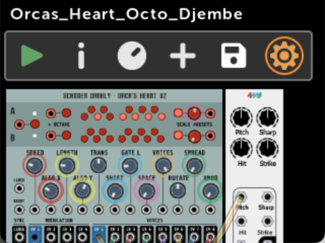
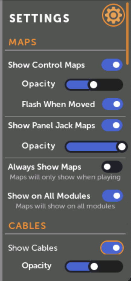
The Patch View display settings menu is found by clicking on the gear icon when viewing a patch.
-
-
Module View display settings:
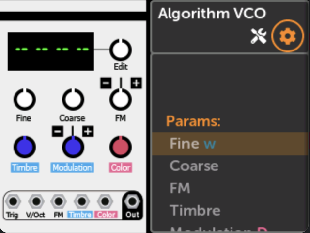
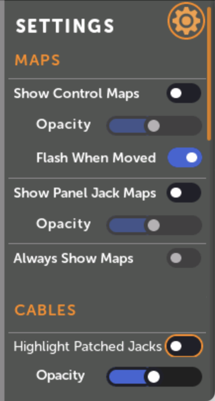
The Module View display settings menu is found by clicking on a module in a patch and then clicking on the gear icon at the top.
-
GRAPHICS
These options control how graphic screens on modules are displayed. The term "graphic screen" is a loose term that refers to any element on the module that's drawn dynamically (besides knobs, sliders, buttons, switches, lights, and text displays). This may refer to anything from waveform or BPM displays, to static portions of the faceplate that the module designer chose to draw with vector commands, to text under knobs that may change in different modes.
-
Draw Screens: toggles whether to draw graphic screens on modules. If you have issues with the module responding slowly to the rotary encoder and Back button, then try disabling screens or adjusting the Update Rate.
-
Update Rate: When screens are enabled, you can throttle the frame rate with this option. When set to the maximum value (fully to the right), each graphic screen in the patch will be updated in turn, one graphic screen per 60Hz refresh. Each click of the slider to the left updates screens half as often (i.e. one screen per 30Hz refresh, then 15Hz refresh, etc..)
STATUS BAR
The status bar is visible in the upper-right corner of the Patch View, and the upper-left corner of the Module View. It displays the current CPU usage, and optionally the audio sample rate and block size.
-
Show Audio Settings: This option shows the current audio sample rate and block size in the status bar before the CPU load. For example,
48k/128 33% -
Show Status (Module View) / Show Status on Top (Patch View): When enabled, the status bar will always be on shown in the corner, on top of everything else, even if the page scrolls.
Patch View only
- Show Knob Set Name: This displays the name of the current Knob Set next to the patch name.
NAVIGATION
Module View only
- Allow Wrapping: When enabled, navigating in ModuleView with the rotary encoder wraps around. Scrolling past the last item in the control/jack list jumps to the button bar at the top, and scrolling backwards past the buttom bar jumps to the bottom item in the list of controls. When disabled (the default), navigation stops at the ends of the list.
MAPS
These options set how control mappings (knob, switch, and button maps) are displayed:
-
Show Control Maps: toggles whether to hide or show a colored ring around controls that are mapped. The color corresponds to the panel knob it's mapped to.
-
Opacity: How opaque or transparent to draw the colored rings.
-
Flash When Moved: Whether to flash the colored ring when its panel knob is moved. This can be turned on even if Show Control Maps is off.
-
Show Control Aliases: (Module View only) When enabled, the alias name for control mappings will be displayed next to the control name in the element list.
These options set how jack mappings to the panel are displayed:
-
Show Panel Jack Maps: toggles whether to hide or show a colored circle on jacks that are mapped to the panel. The color corresponds to the panel jack it's mapped to.
-
Opacity: How opaque or transparent to draw the circles. If Opacity is more than about 40%, the number of the jack will be drawn inside the circle.
-
Show Jack Aliases: (Module View only) When enabled, the alias name for jack mappings will be displayed next to the jack name in the element list.
This option refers to both control mappings and jack mappings:
-
Always Show Maps: Enabling this option will hide control and jack maps when you are viewing a patch while a different patch is playing (or paused). This option is disabled if both Show Control Maps and Show Panel Jack Maps are off.
-
Show on All Modules: (Patch View only) When this option is enabled, maps will be drawn on all modules in the patch. When this is disabled, maps will be drawn on only the module that's currently focused. This option is disabled if both Show Control Maps and Show Panel Jack Maps are off.
Cables
-
Show Cables: (Patch View only) Toggles whether to draw cables connecting modules.
-
Highlight Patched Jacks: (Module View only) Toggles whether to draw a colored square on jacks that have an internal cable patched to them. Output jacks have a square drawn around the outside of the jack, and input jacks have a square drawn on the inside of the jack. The color of the square matches the color of the cable as seen in the patch view.
-
Opacity: How opaque or transparent to draw the cables or squares.
Patch Info
-
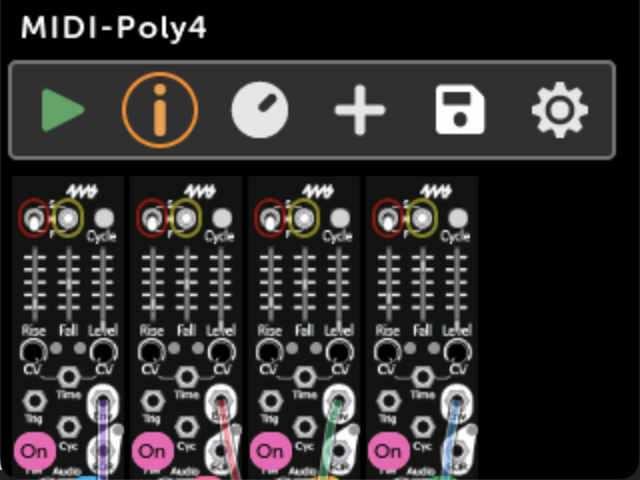
Patch Info
The Patch Info window is opened by clicking the
(i)info icon when viewing a patch. -
-
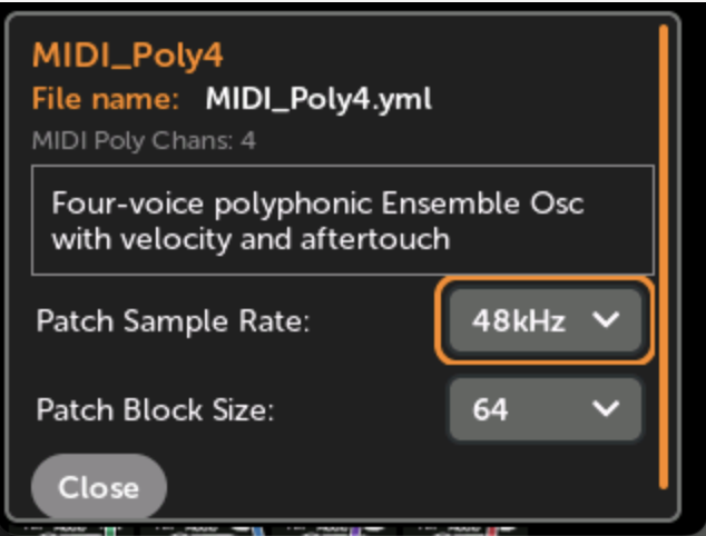
The Patch Info window contains information about the patch:
- Patch name
- File name
- MIDI polyphony channels (if relevant)
- Patch description
- Patch's sample rate and block size
-
-
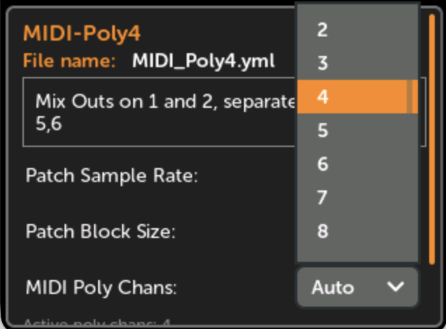
MIDI Poly Chans
If the patch uses MIDI, the Patch Info window includes a MIDI Poly Chans setting that controls how many voices of MIDI polyphony the patch uses:
-
Auto (default): the number of voices is detected automatically from the patch's MIDI mappings.
-
1 – 8: force a fixed number of voices.
The Active poly chans line below shows how many voices are currently in use. See MIDI Polyphony.
-
-
-
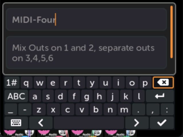
Patch Description
Click on the description to edit the text.
-
-
Patch Sample Rate and Block Size
You can set the suggested sample rate and block size for each patch. When the "Allow Patch to Override" preference is enabled (see preferences), the sample rate and block size will automatically be set to these values when the patch is loaded.
Changing these values while the patch is playing will immediately change the current sample rate and block size.
You can also set these values from VCV Rack when creating the patch: see Setting Suggested Audio Settings.
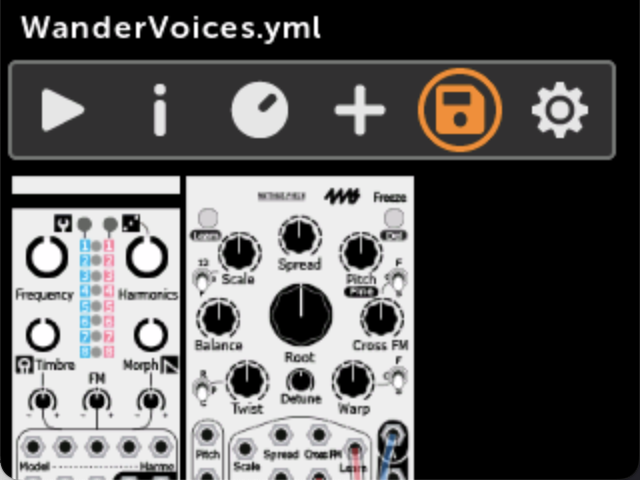
Patch File Menu
-
Patch File Menu
The Patch File Menu is opened by clicking the file/disk icon when viewing a patch.
While focused on the file icon the file path will be shown.
-
-
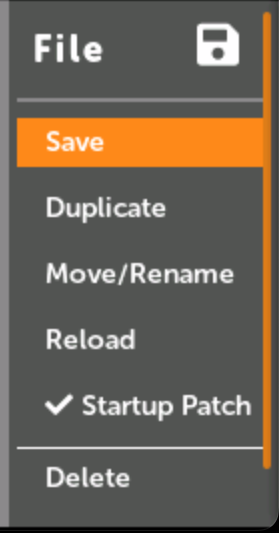
Save, Duplicate, Move/Rename, Reload (or Revert), Startup Patch, Load on MIDI PC, Delete
-
-
Save: save the patch file
This will save the current state of the patch including the position of all knobs, switches, and buttons. All mappings will be saved.
If you ejected the disk, then the patch will not save (an error will be shown). In this case, either re-insert the disk and click
Saveagain, or clickDuplicateto save in a different location.
-
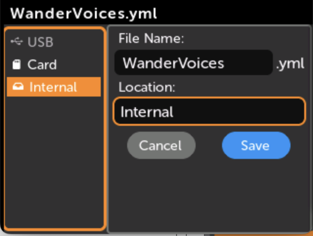
Duplicate: save a copy of the patch
Clicking this will bring up a window where you can set the patch name and/or disk or sub-folder of the new patch file.
The new patch file will be opened after the old one is duplicated, but if the old one was playing, the old one will still be playing.
-
-
Move/Rename: change name or location of a patch
Clicking this will bring up a window where you can change the patch name and/or disk or sub-folder.
-
-
Revert (or Reload): Revert all changes to the patch file
This will reload the patch file from disk, losing all changes. It cannot be undone.
If you ejected the disk that the patch file lives on, then the patch cannot be reverted since the original file cannot be loaded.
This option will appear as "Reload" when you have not made any modifications to the patch, and "Revert" when you have modified the patch. The resulting action is the same (reloading the file from disk).
-
Startup Patch
Select this menu item to toggle whether the patch is the startup patch.
When the MetaModule is powered up, the startup patch will be loaded and played after plugins are pre-loaded.
If you don't want to have a startup patch, uncheck this.
You can see what patch is the startup patch, and/or disable any patch from playing at startup in the Preferences.
-
Load on MIDI PC: Assign this patch to a MIDI Program Change number
Choose a PC number (0–127) and MIDI channel. When MIDI PC Patch Load is enabled in the preferences, sending that Program Change message from a MIDI controller will load this patch.
-
Delete: Delete the patch file
This will delete the patch file from disk. It cannot be undone.
If you ejected the disk that the patch file lives on, then the patch cannot be reverted since the original file cannot be loaded.
File Names:
The legal characters for file names are: 0-9 A-Z ! # $ % & ' ( ) - @ ^ _ `` { } ~ + , ; = [ ] and extended characters \x80 to \xFF and U+000080 to U+10FFFF White spaces and dots can be placed anywhere in the path name except end of the name. Trailing white spaces and dots are ignored.